A Portable D-Star Hotspot – DV-Mega and Raspberry Pi

Here’s what I put together in my lunch hour today (and I’m not even kidding – it took way less than an hour to get this thing up and running!):

DV-Mega RaspberryPi

It’s a portable D-Star Hotspot that allows me to access International D-Star Reflectors wherever I am, independent of repeater coverage.

It works really well and I’ve been listening to people from all over the world chatting to each other this afternoon, via my Icom ID-51 handheld, this standalone device and a WiFi connection (tested with my home broadband and using 3G tethering from my iPhone 6 Plus).

It’s made up of the following components:

  • Raspberry Pi Model A+ with Pimoroni Pibow Coupé Case (link)
  • USB 802.11n Nano WiFi Adapter (link)
  • 16GB Class 10 Micro SD Card loaded with the DV-Mega.co.uk Image and Software (link)
  • DV-Mega Pi Radio Shield (70cm DV Modem that attaches to the RPi via the GPIO header) (link)
  • Official Raspberry Pi Power Supply (link)
  • iGO 4700mAh 5v Battery Bank (couldn’t find this for sale any more, so this is a link to something similar)
  • Nagoya NA-666 SMA 144/430 MHz Antenna (link)

I ordered the DV-Mega PI Shield and Pre-Configured 16GB Micro SD Card from Karl, M0KSP who is based in Sheffield, UK and it arrived next day via Royal Mail Special Delivery.

First I mounted the Raspberry Pi A+ in the Pimoroni case and inserted the Micro SD card.

I then cut the nylon hexagonal stand-off (supplied with the DV-Mega) in half and superglued it in the correct position on top of the Pibow case, so that the DV-Mega can be screwed down when placed on to the RPi’s GPIO pins. After which I screwed down the antenna.

I then temporarily connected the Pi to my monitor using an HDMI cable and connected a USB Hub to the RPi, so that I could connect a keyboard, mouse and the WiFi Adapter.

Once everything was connected, I applied power to the RPi.

After the RPi booted up and the GUI appeared on my monitor, I set up my WiFi connections (both home and mobile) using the WiFi Config tool on the desktop.  I then cleanly shut down the RPi, removed the power and disconnected the HDMI cable and USB Hub, then attached the WiFi Adapter directly into the solitary USB socket on the RPi.

I set some new memory items up on my ID-51, following the Maryland D-Star Group guide (link) and then powered the RPi back up.

There are no activity lights on the DV-Mega PI Shield to tell you what’s going on, but when your radio is on the right frequency, you’ll hear it announce that the Hotspot is active (mine automatically connects to a reflector when booted up).

From then on, you don’t need to touch the RPi, as you link and unlink to/from reflectors using memories on the radio.

You can also reboot and halt (shut down) the RPi using memories on the radio too!

Anyway, there you have it…  A pretty inexpensive way to connect to the D-Star network while out of range of a “proper” repeater, or if you like rag-chewing and don’t want to hog your local repeater!

There’s lots more info on the internet, so if you need more help, Google is your friend!

Let me know if you want a QSO on one of the D-Star Reflectors once you have your hotspot up and running!  You can contact me on Twitter: @JoshMurray .

73 for now!

Josh de M0JMO

AA6E’s Tiny Python Panadapter on a Raspberry Pi

20140420-203735.jpg

Well, what a learning curve this has been! After about 20 hours work, and a bit of expense, I now have a working Panadapter / Waterfall for my Elecraft KX3.

Is it a PX3? Of course not, but it shows what is happening around the frequency I’m listening to (good when trying to make contact with a DX Station working split), it’s a fraction of the price and is available now. I still have a PX3 on order though!

20140420-203947.jpg

Here’s a quick video of it working (on Instagram):

I am a total newcomer to Linux, Bash Scripts and Python programming, but with lots of Googling, some emails from friendly amateurs, patience, coffee and beer, I muddled through and have a working device. Because I’m kind; I’ve documented the entire process for you to follow 🙂

Click to access M0JMO-Tiny_Python_Panadapter-Raspberry_Pi_Setup_Guide-v1_2.pdf

Have fun and let me know when you get yours working! I’m @JoshMurray on Twitter.

Another Buddipole Upgrade!

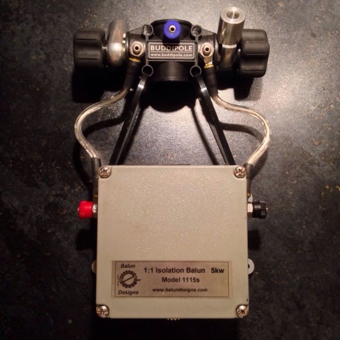
Following on from my last post, I put my FrankenBuddiPole up in the garden this afternoon and it worked just fine, but then I realised the Triple Ratio Switched Balun has a maximum power rating of 150w, which while perfect for field use, is a bit low for use at home. So, I decided to perform another upgrade!

Enter the BalunDesigns 1:1 Isolation Balun, with a 5KW power rating!

Here she is:

20140111-212323.jpg

Cheers

Josh

Buddipole Antenna Repair and Upgrade

I’ve owned a Buddipole antenna of some form or another for a number of years and have steadily upgraded it, spending a frankly silly amount of money along the way to create a pretty portable and fairly well performing multi-band HF antenna.

In it’s current form, it works well from 80m to 10m, thanks to replacement “Silver Bullet 1000” coils from Wolf River Coils and the long black telescopic whips from Buddipole.

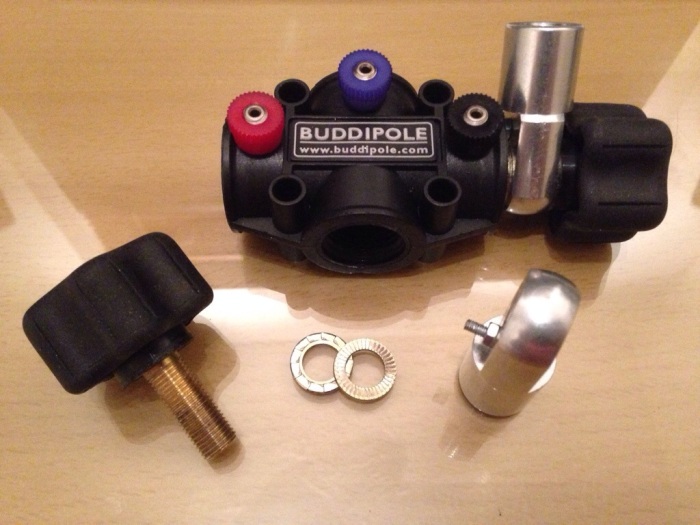
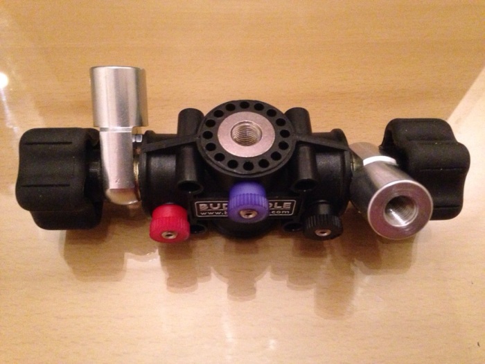
I had already replaced the original centre piece with the stronger “VersaTee” to help support the added weight, but had to stop using the original Rotating Arm Kit as they would no longer stay in place.

This summer, while demonstrating the antenna in my garden to a visiting amateur, I let the painters pole mast down a little too quickly and the abrupt stop at the bottom caused one of the whips to snap at the base (even with the knurled base accessory installed) and both the arm tubes to bend and come away from the plug/screw at the end. Upset at my rookie and costly mistake, I mothballed the antenna over the autumn and only got it out yesterday to see what I could do to fix it.

I decided to drill a hole through the ends of the arms and whip, through the tube and aluminium / copper end plugs, then insert a screw and nut though the hole to keep it all secure. This is the result which I’m quite pleased with:

20140109-124409.jpg

I then thought I’d tackle the Rotating Arm Kit to see if I could make it more like the new revised version that Buddipole sells, which has pins that lock into the VersaTee to stop it rotating. A bit of measuring, drilling and screwing later and this is the result, which works great!

20140109-124655.jpg

20140109-124635.jpg

20140109-124623.jpg

A good evening’s work if I do say so myself 🙂

I’ll hopefully be able to get it back on the air this weekend!

Cheers

Josh

Hardrock-50 HF Amplifier Power Output

80m
1.8w = 50w on meter
Shows 55w on screen
Input SWR = 1.3:1

40m
2.6w = 50w on meter
Shows 55w on screen
Input SWR = 1.2:1

20m
2.6w = 50w on meter
Shows 55w on screen
Input SWR = 1.3:1

17m
5w = 50w on meter
Shows 54w on screen
Input SWR = 1.4:1

15m
3.2w = 50w on meter
Shows 55w on screen
Input SWR = 1.5:1

12m
4.2w = 50w on meter
Shows 55w on screen
Input SWR = 1.8:1

10m
3.4w = 50W on meter
Shows 55W on screen
Input SWR = 1.9:1

6m
5w = 30w on meter
Shows 35w on screen
Input SWR = 4.6:1

Hardrock-50 HF Amplifier Build Complete!

Today I finished building my Hardrock-50 50w HF Amplifier kit. It was pretty-much done yesterday, but needed a few final tweaks to complete.

I haven’t photographed every stage of the build process, but I’m sure you’ll get the gist of it! Apologies for the quality of these photos too… I was in solder-mode rather than photography-mode, so they’re not well lit or composed I’m afraid.

Continuing on from my previous blog post, I started by winding the torroids. My fingers hurt after doing these, and working with PTFE covered wire is a pain in the bum! There’s a fella in the US that can sell you a complete set of pre-wound torroids for a nominal fee, but where’s the fun in that?

20140104-174141.jpg

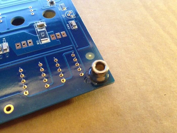
Next was soldering the metal stand-offs to the main board which was easy:

20140104-174236.jpg

Here you can see the bottom of the main board after I had soldered in all the through-hole components:

20140104-174333.jpg

And here is the top of the main board. A couple of the torroids were really fiddly to attach.

20140104-174422.jpg

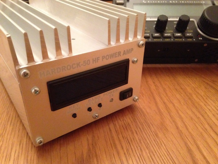
This is the main board attached to the heatsink with the front and rear panels connected. The only big problem I had was that I snapped the drill bit while drilling the second to last hole, so the main board is only attached at the rear (but it isn’t going anywhere!)

20140104-174901.jpg

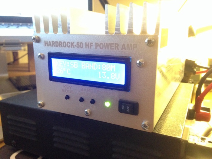
Here it is, alive!

20140104-175014.jpg

This photo shows me on the air with it for the first time last night:

20140104-175033.jpg

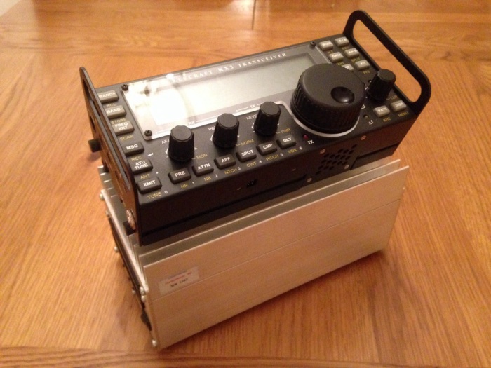
I’ll write another quick blog post later on showing the amplifier case in more detail and along side my Elecraft KX-3 (my photos haven’t synced via iCloud yet!)

Cheers

Josh

Hardrock-50 HF Amplifier Build – Day One

20140101-161932.jpg

Today I started to build my Hardrock-50 (HR-50) HF Amplifier Kit, which I got for Christmas from my Mum and myself.

The first thing to do was to replace two SMD capacitors on the main board (C5 and C31) because the factory installed incorrectly rated parts.

I can’t remember ever replacing any SMD components before, so this was quite unnerving; however once I got the main board into my PCB holder, fired up the Weller and found my wife’s tweezers from the bathroom, I was all set and didn’t find it too difficult after all.

20140101-162536.jpg

Next I fired up the PDF manual on my computer and started following the steps to the letter!

First up was the front panel with the LCD and buttons. This was pretty straightforward. The header pins were pretty close together and the rings to solder to on the PCB are minute, but it didn’t take long to complete.

20140101-162833.jpg

20140101-163128.jpg

20140101-162845.jpg

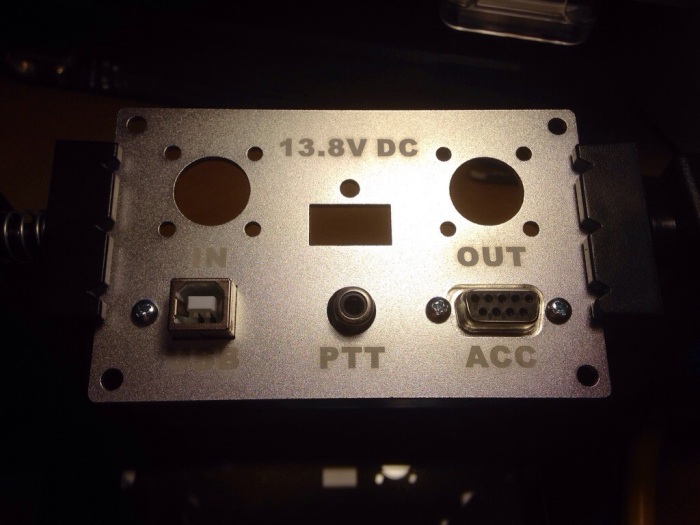
Next up was the rear panel, which was more straightforward and didn’t take long to complete. I guess the SO239 sockets and Anderson Power-Pole socket will be installed later.

20140101-163055.jpg

20140101-163226.jpg

That’s it for today… Next stop torroid / inductor winding! I want to get rid of this flu virus entirely before attempting those!

Cheers, Josh!